For our performance-minded members, here is some overwhelmingly comprehensive information compiled by Drac about returnless fuel system builds. The original thread is here.
This is a write up discussing my highly fortified returnless fuel system I constructed that was built to pretty much withstand any HP level I could readily throw at it, at or within the 1,000 RWHP range. (estimate based off of components used and numbers other people hit with a similar setup) I have had these parts bought and sitting around for well over year, and never installed them because it wasn’t a necessity. I’m doing it now just to get it out of the way. It is built with a high level of redundancy and offers failsafes for every component- thus every component has its own relay, fuse and large gauge power lead feeding it. Nothing is piggy-backed and most components work in a standalone fashion, for what it's worth.
Fuel is obviously a major key player on any high HP build, and is something not to be overlooked. I massively overbuilt mine for 2 reasons: Immediate capability of being able to readily handle pretty much anything I can throw at the car, and two: for simple peace of mind. At around 700 RWHP @ WOT- Fuel pump duty cycle should only be at or around 75%. Before all this, I was reaching 95% duty cycle on one Aeromotive pump and no BAP at 417 RWHP. Since the car is still down pending blower repair, I can’t test FPDC at my current HP level.
Also, one of the best things about the way this layout was executed, is I can unplug the main Logic pigtail and plug this back into the master fuel pump driver module and effectively revert the entire car back to stock in less than 10 seconds. I will explain this later.
A big thanks to Travis (Musclemerc) for helping me out with this. I looked at his fuel system build as a superstructure for the construction of mine, and made some changes in certain places with mine to accommodate my own personal taste. Since I figured some people may want a basis on how to construct a potent/stout returnless system (with the influx of boosted/ High HP panthers we are now seeing) maybe this will help as an overview to some of you that don’t want to go to a return style. (2003+)
Obviously, a lot of people argue that return style is better for various specific reasons. I’m not disagreeing with any of those reasons. But I opted to stay returnless for my own personal justifications.
This is a compiled parts list detailing the main structures used in the design of this fuel system superstructure:
-Dual OEM FPDMs (Fuel Pump Driver Modules)
-Custom made harness supporting both FPDMs that makes them both plug and play effectively.
-Dual Aeromotive Stealth 340 LPH Pumps, both on separate and isolated channels/lines
-Full wiring upgrade
-Kenne Bell dual 40A Boost-A-Pump (GT500 BAP) with an adjustable hobbs switch
-Customized hat to accommodate 2x pumps
-Dual PPRVs (Positive pressure release valves)
-Full fuse block in trunk giving every component fused protection
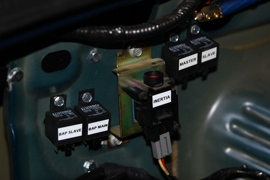
-4x relays (2x for FPDMs, 2x for dual BAP)
-Dual 6AN braided line all the way to the rail
-Dual 20 Micron in-line fuel filters
-80lb/hr Siemens Deka Injectors
Again, thanks to Travis (Musclemerc) for assisting me in figuring out some of the odds and ends and being nice enough to send me some PTFE certified in-tank wire, twisted pair 12GA for the 2nd pump and pointing me in the right direction for the bulkhead fitting. Besides reflecting on his schematics as a basis, I also used the layout below as a basis for this project, but added 2x additional relays for each FPDMs. The BAP output now goes into the FPDM’s relay’s main fused power in opposed to going straight to each FPDM respectively.

This image represents the wire routing from the main FPDM plug to the master and slave respectively. I just added a 2nd relay so each FPDM has its own relay

The BAP and FPDM relays (all 4 of them) all use the 12v lead going into the inertia switch as their trigger to power on as soon as the ignition is turned on. The entire system gets its main logic power from an 8-gauge main power lead coming straight from the battery that has an initial 40A fuse on it. From here, it splits into 2x 10-gauge main power feeds that power the BAP relays. Each of these 10-gauge wires are protected with a 30A fuse on the same block. From here, the BAP output goes back into the fuse block with two more 30A fuses before going to the 2x FPDM relays (Still utilizing 10-gauge wire here) Finally, from here, the FPDMs send their power to the 2x Aeromotive pumps using upgraded/thicker wiring then stock. All power leads from the fuse block to all accessories are 10 gauge, save for the main logic power, that like I said was 8 gauge.
Below is an overview of the main fuse block. The third to last circuit is to a trunk mounted power point that does not have any relation to the fuel system. Aux 1 and aux 2 are spares and not used and are readily able to accept any circuit with up to a peak of 15A, based on the wiring used for the power on these channels.
Channels are as follows:
SYSTEM MAIN POWER IN (40A FUSED PROTECTION)
FPDM (MASTER) (30A FUSED PROTECTION)
FPDM (SLAVE) (30A FUSED PROTECTION)
BAP (MASTER) (30A FUSED PROTECTION)
BAP (SLAVE) (30A FUSED PROTECTION)
POWER POINT (10A FUSED PROTECTION)
AUX 1 (NOT USED) (15A FUSED PROTECTION)
AUX 2 (NOT USED) (15A FUSED PROTECTION)


Here are a few pictures before the custom made harness, slave FPDM and BAP were installed. You can see the custom mount I made to mount the BAP to (two black bars protruding out) I have the relays affixed in this picture also as you can see.


In these next pictures, you can see the construction of the harness before the split loom was put on. You will notice larger gauge wires in this, which are power leads going to/from the relays, and the fuel pump wires going from the master/slave plugs to the main logic plug that plugs into the OEM plug on the car. This harness plugs into the OEM FPDM pigtail on the car and has all of the relay integration in it for the FPDMs and the BAP, the master/slave plugs integrated in it as well as the relay’s power leads that go to the fuse block.


At this point, I put split loom on the main harness and taped it up. Here are pictures of it ready to install.


Harness and BAP installed and all wires ran.


 (CONTINUED BELOW)


 Previous Topic
 Index
Index

 Your Privacy Choices