These posts contain information on upgrading the AODE/4R70W/4R75W/4R70E/4R75E transmissions used on 1992.5+ up panthers for improved performance and durability.
The first post (below) contains general information on the "J-MOD" modifications and some notes for 1998 and newer model owners who will be performing the upgrade.
The second post provides reviews of some of the possible accumulator spring changes asscoiated with the jmod, courtesy Blue95
The third/last post is a write-up on performing the upgrades, specifically on -1997 model 4R70W transmissions, but can be used as a guideline for most years. Courtesy Redmobile.
-------
This article describes upgrading a 1998+ 4R70W using tips from 4R70w guru Jerry. It is meant to be used as a supplement to the J-MOD articles found here:
http://www.tccoa.com/articles/tranny/index.htmlFor -97 AODE/4R70W owners, perform the J-MOD transmission upgrades as outlined in the link above.
Note, For 2005+ panthers the 4R70E (4R75E for 06+) is used. At this time I am unsure if these steps still apply.
Please refer to this BOK article for more accumulator spring info:
J-Mod Accumulator Spring review - by Blue95The following article was authored by member
HookedOnCV, with notes from member
Marauderer=================================================Ford 4R70W Transmission upgrade (J-Mod) for late model (1998
and newer) Crown Vic/Grand Marquis/MarauderInstallation notes by Bill Bowker (Marauderer) Presentation by Todd Stafne (HookedOnCV)
� 2004 CrownVic.Net The following notes were compiled from forum posts by Bill Bowker while he was in the
process of modifying his 2003 Mercury Marauder�s transmission. The J-Mod has been
performed by many people on the 4R70W transmission using the detailed articles found on
TCCoA.com, however no updates to the article have been published specifically for the late
model Panther platform cars. Over the past several years, Ford has made many of the
improvements called for in the TCCoA article and this presentation summarizes the suggested
changes for our current application.
Please refer to the detailed article posted on TCCoA�s website to gain a full understanding of
what it is you are trying to accomplish with the J-Mod. You will get much more information
pertaining to the overall modification than what is presented here. Use this document only as
a supplement to TCCoA�s transmission article.
I met with Jerry W. this Saturday in Detroit and asked him about his J-Mod for our cars. He
sent me this picture and these updated instructions for late model cars.
"
Ignore what the article says and do this...
>
> Remove the bottom 1-2 accumulator spring and remove the bottom 2-3
> accumulator spring.
>
> For holes do this.
>
> Hole #2 is the intermediate clutch feed (1-2 shift). Make this hole in the
> .100"-.110" range. It should be .081" in your plate right now.
> Hole #10 is the reverse clutch feed. Totally optional. If you want it to
> engage into reverse faster when you move the lever, open this up to .093".
> Holes #4 & 5 are the direct clutch feed (2-3 shift). Open both of these
> holes up to .100"-.110".
> Holes #9 and 11 are the forward clutch feed (4-3/4-2 shift). Make both of
> these .100-.110" as well.
>
> So, it looks like you need a drill of around .100" and you should be good.
> When you open up holes 4&5 make sure the hole in the gasket between the
> separator plate and valve body casting, is large enough. These holes are a
> little small.
>
> jerry"
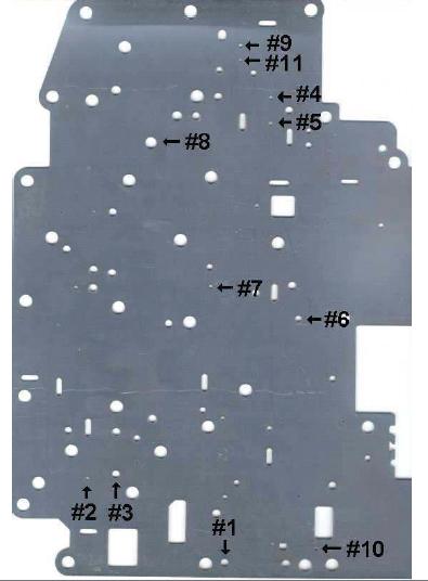 Figure 1
- Tools:
- 3/8 drive inch pound torque wrench
- 3/8 to 1/4 drive adapter
- snap ring/retaining ring pliers
- Deep well 10mm socket (1/4� drive)
- Standard depth 8mm socket (1/4� drive)
- Pliers
- Cordless drill with clutch
- Drill Press (or drill) and drill bits (separator plate mod)
- Oil drain pan
- Exacto knife or razor blade
- (2) Separator Plate Gaskets
- 1W7Z-7D100-AB
- 1L3Z-7C155-AA
-Note: about 2.00 each
- transmission fluid filter (Motorcraft FT105)-d
- approximately 8 quarts of transmission fluid (Mercon V!)-d
- Dielectric Grease
- Vaseline
- Carb or brake cleaner
- Sanding stone or knife sharpening stone
- Jack, Stands, Lights
- Step I:
- Disconnect the transmission cooler return line where it changes from a hose to a steel line.
There are two lines coming out of the cooler, you want the upper one. Follow it down; it
should still be the upper line at the point of change.
Note: Look under the passenger side, it is in between the frame and the lower crank pulley. A
quick squeeze of the pliers to move the clamp and you�re done. - Have someone hold it steady and point it into an oil pan. Start the car and let it idle while
the transmission fluid is pumped out in a continuous stream. Shut the car off as soon as the
stream starts to sputter or the flow decreases significantly. - Re-attach the transmission cooler line.
Note: This would be a great time to drain the torque converter if you like.
- Step II:
- Jack up the front of the car and place it on jack stands for safety.
- Step III:
- Remove the transmission pan by loosening the 14, 10mm pan bolts.
- You�re best bet is to use a cordless drill with a 1/4 � socket drive adapter and a deep well
10mm �� drive socket (you use a �� drive because anything larger will not fit between the
frame and the rear of the pan.
- Drop the pan
- There will be very little fluid left in the pan. You can let it down carefully without fear of
spillage. The messy part comes later. - 4 - 5 items should fall into the pan; a little yellow plastic plunger (discard, it was a temporary plug from the factory), the 2-3 accumulator spring (set aside it does not go back
in), a metal base for the spring (save), possibly the 2 � 3 shift accumulator itself (a larger
plunger with a smaller diameter top and larger diameter bottom, and oval shaped filter. - Remove the filter; remember to pull out the rubber grommet as it usually sticks.
- Step IV:
- Remove the valve body
- Prep: layout a canvas under your car, layout a couple of paper towels under the car to set
the valve body on later, layout a couple of paper towels on your workbench to receive the valve body once it is removed.
- Start by removing the black plastic harness from the valve body. It snaps into place in 3-4 locations and is removed with a slight tug at each connection point.
- Towards the upper right, remove the bolt with the rooster comb spring (has a roller attached to it ), makes sure to keep the bolt in the hole of the spring as to not lose the orientation of
either piece. - Adjacent to this is another bolt with a metal bracket, remove this in a like manner.
- Now take a look at the valve body and notice that there are two types of bolts; those with
8mm heads and those with 10mm heads. Do not concern yourself with the 10mm bolts. Look
closely at the 8mm heads and you will notice that the ones in the middle section (plate
section) will be a bit longer than those on the periphery. When putting them back, the longer
ones go in the plated section and the shorter ones go around the periphery. - Remove the periphery bolts (using a cordless drill, an a 8mm socket)
- Note the position of the manual valve. It is the piston looking thing and has a notch in it in
which a pin on the detent lever resides. - Remove the bolts in the plated section, all but one in the center most section.
- Now get your drain pan ready as here comes the tranny fluid shower
- Slowly back out the last bolt about a quarter of an inch and wiggle the valve body slightly so
that tranny fluid starts flowing. - Let this drain for 15 � 20 minutes (should be about 3-4 quarts).
- Once the fluid has drained, or you get tired of waiting, hold up the valve body and unscrew
that last bolt. Hold it firmly and be prepared as it is heavy than it looks and if your car is not
jacked up high enough you will have little leverage. - Place the valve body on your workbench, gasket side up.
- Step V:
Disassembly and Modification. - Use an exacto knife or razorblade to lift a corner of the gasket and remove carefully.
- Note the orientation of the two reinforcement plates (circles with 4 bolts each)
- Remove the 4 bolts from each plate with a 10mm socket and place on a paper towel in the same pattern as they were prior to removal.
- Remove the one 10mm bolt that holds the separator plate in place.
- Remove the two plates and place them in the same orientation they were prior to removal (clean with carb or brake cleaner).
- Remove the separator plate and clean with carb or brake cleaner.
- Drill the holes as prescribed in Jerry�s document (Figure 1)
- I drilled mine to the following specs:
- Holes #2, #4, #5, #9, #11 � 7/64 drill bit
- Hole #10 � 3/32 drill bit
- Deburr your drillings with a sanding stone
- Remove the remaining gaskets off the valve body
- Place the new gasket on the valve body
- Clean the separator plate and reinstall
- Install the new top gasket
- Reinstall the circular reinforcement plates (torque to 90 inch pounds)
- Clean the entire valve body paying attention to any electrical connectors
- Apply a small amount of dielectric grease to the electrical connectors.
- It is now ready for re-installation.
- Step VI:
- Under the car; clean the transmission internals with carb or brake cleaner, paying attention to any electrical connectors.
- Using the snap ring/retaining ring pliers remove the snap ring from the 1-2 shift accumulator (the round hole on the drivers side front corner [towards the front of the car])
- Watch out as this ring holds a cover with a spring behind it that is under tension.
- Remove the spring.
- Replace the cover and the snap ring.
- Apply dielectric grease to any electrical connectors.
- Clean the oval filter screen that came out during disassembly and apply a small amount of Vaseline on the black plastic (top) and place it back up in the tranny. There is only one place
for it to go towards the rear right corner. If you look up you will see a space the shape of the black plastic top (a rectangular shape). - The 2-3 shift accumulator may have fallen during the valve body removal. Place it and the spring plate back into the 2-3 shift accumulator hole. The accumulator goes in small end top,
large end bottom. Press it into the hole slightly. Then install the old round spring base; one side is relatively flat and the other has a point; the point goes down. You may have to bend
the tabs out on this piece ever so slightly to get it to stay up in the hole.
- Step VII:
- Now reinstall the valve body.
- Pay close attention to the manual valve (piston looking thing) remember the pin on the detent arm must go just behind the head of the piston.
- Hold the valve body up and place one of the long bolts as close to the center as possible.
- Reinstall the rooster comb spring and metal bracket in their respective locations.
- You can now start the remaining bolts by hand; just a few turns to make sure they are
seated properly and not cross threaded. - Set your cordless drill to the lowest clutch setting (lightest) and set all bolts; using the included bolt pattern diagram at the end of this document (Figure 2)
- Now torque all bolts to 90 inch pounds using the included bolt pattern document (Figure 2).
- Reinstall the black plastic electrical connector, snap it firmly into place and make sure that
each contact point is seated and secure. - Install a new tranny filter (coat the seal with a little tranny fluid).
- Step VIII:
- Reattach the transmission fluid pan (using the original multi-use gasket unless it is damaged).
- You can now start the remaining bolts by hand; just a few turns to make sure they are seated properly and not cross threaded.
- Set your cordless drill to the lowest clutch setting (lightest) and set all bolts (10mm).
- Now torque all bolts to 120 inch pounds.
- Step IX:
- Measure the amount of fluid drained from the system (should be about 8 quarts).
- Fill the transmission through the dip stick tube by the measured amount.
- Confirm your results!
- Hold the brake, start your engine, move the shifter through the gear selections, and allow your car to warm up while checking for anything out of the ordinary.
- Check for leaks.
- Follow precautionary measures and confirm your good work!
 FIGURE 2 NOTE: The author does not assume any responsibility for personal injury, damaged and/or broken materials during the installation of the aforementioned parts. This document is solely designed as a supplement to a Ford Motor Company shop manual. Please use all necessary and prudent safety precautions before and while performing work on your vehicle.-----Article submission courtesy HookedOnCV
Edited by dRock96Marquis
Edit Reason: Converted to UBB and added notes


 Previous Topic
 Index
Index


 Your Privacy Choices